


설계/시공가이드
SUNJOY PLUS, the heating system that is augmented only with benefits customers have always wanted on top of all the benefits of SUNJOY,
which delivers the same warm feeling of the sunlight. SUNJOY PLUS is opening a new chapter of the ceiling-mount radiant heating system.
 Estimation of the Capacity

Simplified Method to Estimate the Required Capacity (Korea oriented Method)
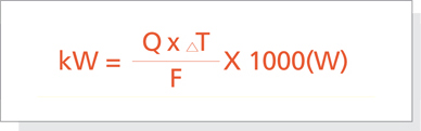
Q: Volume of the Target Space(m³)
T₁ : Initial Temperature Before Heating(℃)
T₂ : T₂: Target Temperature(℃)
△T : Temperature Difference between the Initial Temperature and the Target Temperature(T₂-T₁)
F : Insulation Factor
| Insulation Status | Insulation Factor[F] | Initial Temperature Before Heating | |||
| Excellent insulation (Sauna) | 350 | 22℃ | |||
| Very good insulation (Multi-family residential buildings) | 300 | 19℃ | |||
| Good insulation (Single-family houses) | 250 | 16℃ | |||
| Moderate insulation (South-facing offices) | 200 | 13℃ | |||
| Fair insulation (North-facing offices) | 150 | 10℃ | |||
| Poor insulation | 100 | 7℃ | |||
| Almost No Insulation | 75 | 4℃ | |||
 Outdoor air temperature is assumed to be 10℃.
Once the required capacity is estimated, the models of the panels and their numbers can be determined based on that.
Samples for the Estimation of the Capacity
| Spaces |
|
Height (m) |
Volume (m³) |
Initial Temp[T₁] (℃) |
Target Temp[T₂] (℃) |
Temp. Difference [T₂-T₁] (℃) |
Insulation Factor [F] |
Capacity (W) |
Applicable Panels | |||||
| Public bathrooms (Freeze protection) |
|
2.4 | 36 | 5 | 13 | 8 | 250 | 1,152 | S U N J O Y |
[SR-5D]*2 | ||||
| Residential bathrooms |
|
2.4 | 12 | 15 | 25 | 10 | 300 | 396 | [SR-4D]*1 | |||||
| Small-size offices |
|
2.4 | 32 | 15 | 25 | 10 | 200 | 1,584 | [SR-8D]*2 | |||||
| Patient rooms in hospitals |
|
2.4 | 64 | 12 | 25 | 13 | 250 | 3,307 | [SR-8D]*4 | |||||
| Studio apartments |
|
2.4 | 95 | 15 | 25 | 10 | 250 | 3,792 | [SR-9D]*4 | |||||
| Public bathrooms (Freeze protection) |
|
2.4 | 39 | 6 | 13 | 7 | 150 | 1,837 | S O Y P L U S | [SM-10]*2 | ||||
| Small-size offices |
|
2.4 | 32 | 14 | 25 | 11 | 200 | 1,756 | [SM-7]*2 | |||||
| High-ceiling stores |
|
3 | 89 | 13 | 24 | 11 | 250 | 3,934 | [SM-10]*4 | |||||
| Pension (room) |
|
2.4 | 36 | 17 | 25 | 8 | 250 | 1,152 | [SM-5]*2 | |||||
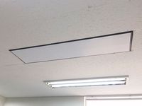
Location shall be determined considering the interference from finished surface of ceiling such as ventilation facility, lights or partitions.
Heater shall be installed with 600mm distance from outer wall, and between heating plates the distance shall be twice than this distance. Various size are available so that it can be installed any space.
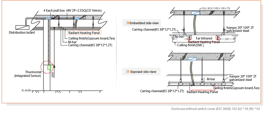
System Design
Installation Diagrams
Thermostats: Types and Circuit Diagrams
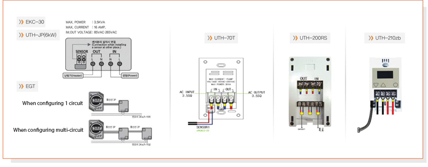
Cetral controll type Thermostat system.
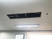
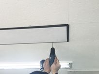
Installation
① Remove "false ceiling" according to product rear part size

②-1 Connecting the lead wire to the Output power wire
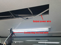
②-2 Close-up of connection part
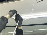
②-3 Termination of connection with insulation tape
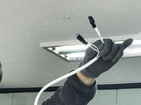
1. Check the heat insulation of the room to be installed, clean the ceiling surface, mark the installation site, remove the ceiling tile according to the size of the product to be installed<Pic ①>, and connect the power cord do. <Pic ②>
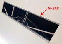
③ Close-up of M bar
④ Fix the heater to M bar
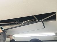
⑤ Screwed to ceiling frame
⑥ Attach closure caps on frame holes
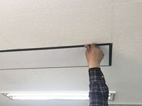
2. Fixed to the ceiling frame (M-BAR or T-BAR) through the frame hole of the product with the screws provided as accessories <Pic ④><Pic ⑤> and finished by putting the Closure caps into the product frame hole where the screw is located, <Pic ⑥>
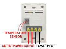
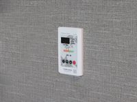
⑦ Rear side of Themperature controller
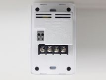
⑧ Wire connection diagram
⑨-1 A case of Installing a Themperature controller on a wall
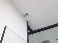
⑨-2 A case of Installing a Themperature controller on a ceiling
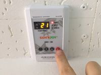
⑩ Check of Themperature controller's operation
⑪ Check of Heating panel's operation